 English
 العربية
 Български
 中文(漢字)
 Čeština
 Dansk
Dansk Eesti keel
 Suomi
Suomi Français
 Deutsch
 Ελληνικά
 עברית
עברית Magyar
 Bahasa Indonesia
 Italiano
 日本語
日本語 한국어
한국어 Latīna
 Latviešu valoda
 Lëtzebuergesch
 Polski
 Português
 Română
 Русский
 Slovenščina
 Español
 Svenska
 ภาษาไทย
 Tiếng Việt


Customize the resolver sensor harness according for EV/HEV drive motor to your drawing or sample requirements.
Dây điện: AF200-T;
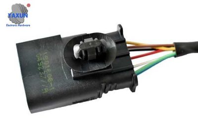
Kết nối: phần cuối;
Ứng dụng: automotive resolver;
Tên: Resolver sensor wiring harness;
Công nghệ chế biến: tán đinh, peeling and tin dipping, cuộc họp;
Customized according to customer needs: wire harness length, thông số kỹ thuật, color, vân vân.;
Dây nịt bên ngoài: fluororubber heat shrinkable sleeve;
Chịu được điện áp: DC300V, 10 mili giây;
Kháng chiến: ≤3 ohms;
Vật liệu chống điện: ≥5 megaohm;
Chu kỳ cắm và rút phích cắm: ≥5000 lần;
Terminal pulling force>40(N);
Hiệu suất sản phẩm: Nhà sản xuất lựa chọn chất liệu cao cấp và sản phẩm có tính linh hoạt cao. Nó có khả năng kháng axit và kiềm, chịu dầu, chống ẩm, chống nấm mốc, chống cháy, chống mài mòn, chống ăn mòn, chất chống oxy hóa, không thấm nước, chống bụi, và chống tia cực tím.
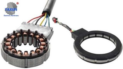
Resolver Sensor Wiring Harness
Chứng nhận sản phẩm: IPC620, IP67, VỚI TỚI, ROHS2.0, MASDS.
Danh hiệu và bằng cấp của công ty: Doanh nghiệp công nghệ cao quốc gia, Gazelle Enterprise, UL, IPC 620, ISO 9001, ISO 14000, ISO13485, IATF 16949, vân vân.
resolver sensor wiring harness for EV/HEV drive motor
1 – Introduction to wiring harness wiring methods
When connecting the resolver sensor wiring harness, you need to pay attention to the wiring methods of the following four lines:
1. Red wire: Connect to the positive pole of the power supply.
2. Black wire: Connect to the negative pole of the power supply.
3. White wire: output analog signal.
4. Green wire: Ground wire.
When wiring, be sure to ensure that the polarity of the power supply is correct, otherwise the equipment may be damaged. At the same time, the wiring must be firm and reliable to avoid loosening or poor contact during use.
After the wiring is completed, a Unicom test must be performed to ensure that the line is correct.
2 – Wiring Precautions
You need to pay attention to the following aspects when wiring:
1. Confirm the model and specification of the wiring harness to avoid mismatch.
2. Check the wiring harness before wiring to ensure there is no damage or wear to avoid malfunction during use.
3. Confirm the wiring position and installation direction to avoid incorrect wiring.
4. Make sure the working environment is dry, dust-free, water-free, and free of any power connections.
Three – Wiring Diagram Example
Below is a resolver sensor wiring harness wiring diagram. Hope this helps everyone understand the wiring method more clearly.
In the schematic diagram, the red arrow represents the positive pole of the power supply, the black arrow represents the negative pole of the power supply, the white arrow represents the sensor analog signal output, and the green arrow represents the ground wire.
【Conclusion】
The above is an introduction to the wiring method of the resolver sensor harness. I hope it will be helpful to everyone. When using resolver sensors, you must pay attention to safety and ensure that the wiring is correct and reliable to ensure the normal operation of the equipment.