제품 카테고리
- 전자 스위치 공급업체 9
- 커넥터 및 케이블 12
- 전원 플러그 제조업체 8
- 의료 진단 케이블 5
- 온도 센서 프로브 0
- 맞춤형 배선 하니스 21
- 사출 금형 제조 7
제품 태그
전기 커넥터 - 와이어 터미널 도관 도구
전기 연결 성능에 대한 일반적인 요구 사항을 충족하는 것 외에도, 전기 커넥터는 양호한 접촉을 달성해야 합니다, 안정적인 작동, 그리고 쉬운 유지 보수. 작업의 신뢰성 여부는 회로의 정상적인 작동에 직접적인 영향을 미치며 전체 전기 제품의 안전과 관련됩니다..
China electrical connector- Wire Terminals supplier, custom and OEM electrical connectors.
전기 연결 성능에 대한 일반적인 요구 사항을 충족하는 것 외에도, 전기 커넥터는 양호한 접촉을 달성해야 합니다, 안정적인 작동, 그리고 쉬운 유지 보수. 작업의 신뢰성 여부는 회로의 정상적인 작동에 직접적인 영향을 미치며 전체 전기 제품의 안전과 관련됩니다..
For this reason, the circuit has very strict requirements on the quality and reliability of the electrical connector. It is also because of the high quality and high reliability of electrical connectors that they are widely used in military systems such as electrical appliances, aviation, aerospace, and national defense. Commonly used classification methods for electrical connectors include shape, structure, and use.
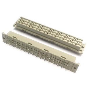 5.08mm 고전류 유럽 소켓 348, 3*16 핀 세 줄 48P |
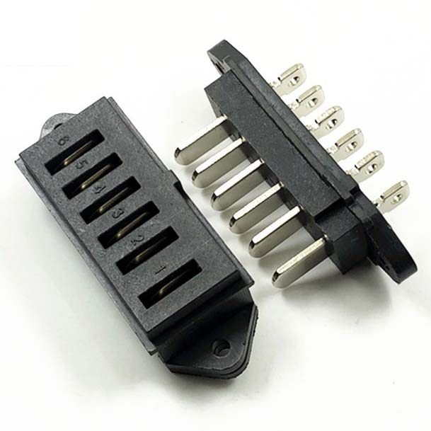
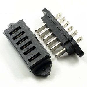 15A male-female new energy high current battery connector |
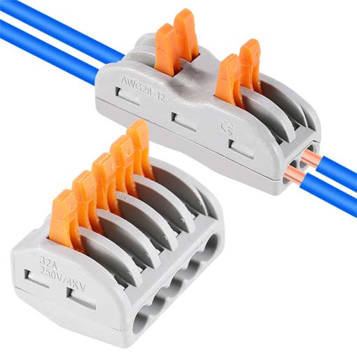
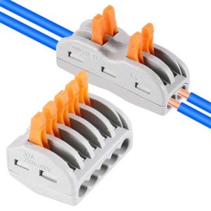 빠른 연결 터미널 일대일 아웃, 아웃 2개, 아웃 3개 |
Classification of electrical connectors
Electrical connectors are classified by shape
Circular electrical connectors, rectangular electrical connectors.
Due to the characteristics of its own structure, circular electrical connectors are the most used in military equipment (aviation, aerospace). Rectangular electrical connectors are more commonly used on printed circuit boards of electronic equipment due to their simple structure.
Classified by structure
According to the connection method: threaded connection, bayonet (quick) 연결, card lock connection, push-pull connection, in-line connection, 등.;
According to the terminal connection form of the contact body: crimping, welding, winding; screw (cap) fixing;
According to the use environment: temperature-resistant, cold-resistant electrical connectors and ordinary electrical connectors.
Classification by purpose
RF electrical connector
Hermetic electrical connectors (glass sealing)
High temperature electrical connector
Automatic fall-off separation electrical connector
Filter electrical connector
Composite electrical connector
Airport power connector
Electrical connectors for printed circuit boards, 등.
The structure of the electrical connector
The electrical connector consists of a fixed-end electrical connector, that is, a female contact (referred to as a socket), and a free-end electrical connector, that is, a male contact (referred to as a plug). The socket is fixed on the electrical parts through its square (round) plate (some of them also adopt welding method). The plug is generally connected to the cable, and the plug and socket are connected through the connecting nut.
The electrical connector is composed of three basic units: the shell, the insulator, and the contact body.
electrical connector housing
The electrical connector housing refers to the shell of the plug socket, the connecting nut, and the tail attachment. The function of the shell is to protect the internal parts of the electrical connector such as the insulator and the contact body (the general name of the pin and the jack) from being damaged. The positioning keyway above ensures the positioning of the plug and socket. Connecting nuts are used for plug socket connection and separation. Tail attachments are used to protect the conductor from damage at the contact termination and to secure the cable. The casing also has a certain electromagnetic shielding effect.
The shell is generally made of aluminum alloy processing (machining, cold extrusion, die-casting). Steel connector shells are mostly used for glass sealing and high temperature resistant electrical connectors.
Insulators for electrical connectors
It consists of a pin insulator and a jack insulator. Interface sealing body, sealing line body and other components. It is used to keep the pin socket at the set position, and to electrically insulate each contact body and each contact body from the housing. Sealing measures are obtained by adding an insulator and an interface sealing body to improve the environmental resistance of the electrical connector.
In order to adapt to the product’s high temperature resistance, low temperature resistance and flame retardancy, it ensures that the geometric dimensions of the parts are stable and reliable. Insulators are mostly molded from thermoset plastics. The interface sealing body and line sealing body are formed by molding silicon rubber.
contacts of electrical connectors
The contact body includes a male contact and a female contact, sometimes also called a pin socket. The connection methods are divided into welding type, crimping type, press-in type and winding type, 등., to realize circuit connection.
The pin socket is a key component of the electrical connector, which directly affects the reliability of the electrical connector. Most of the pin sockets are machined from elastic copper alloy materials with good electrical conductivity. The surface is silver-plated and gold-plated to achieve the purpose of small contact resistance and anti-corrosion. Jacks generally include split slot jacks, wire spring jacks, crown spring jacks and punching jacks.
The structural features are: environment resistance; bayonet type (quick) 연결; multi-key connection (wrong insertion); contact body and wire crimp connection. The shell plus shielding ring ensures 360° electromagnetic interference shielding capability.
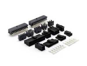 Wire-to-Wire Connector
|
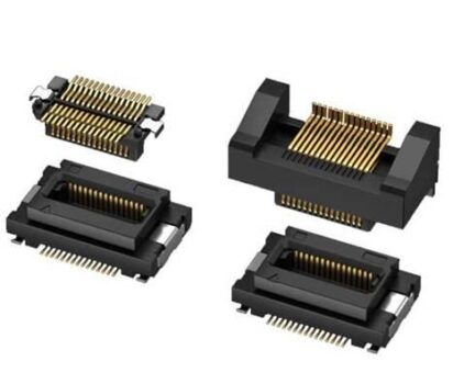
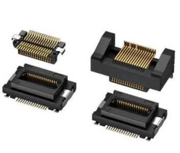 Board-to-Board Connector |
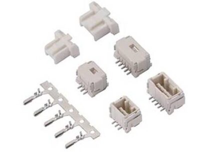
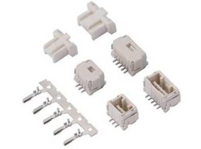 Wire to Board Connector |
Safety parameters of electrical connectors
Insulation resistance
Insulation resistance refers to the resistance value that occurs when a voltage is applied to the insulating part of the connector to cause leakage current in or on the surface of the insulating part. It is mainly affected by factors such as insulating materials, temperature, humidity, and fouling. Insulation resistance values provided on connector samples are generally index values under standard atmospheric conditions. Under certain environmental conditions, the insulation resistance value will drop to varying degrees. In addition, attention should be paid to the test voltage value of insulation resistance. According to the insulation resistance (MΩ) = voltage applied to the insulator (다섯) / leakage current (μA) to apply different voltages, there are different results. In the test of the connector, the applied voltage generally has three levels of 10V, 100다섯, and 500V.
Rated voltage
The withstand voltage is between the mutually insulated parts of the contact pair or between the insulated part and the ground. The critical voltage that can withstand higher than the rated voltage within a specified time without breakdown. It is mainly affected by contact pair spacing and creepage distance and geometry, insulator material and ambient temperature and humidity, atmospheric pressure.
Mechanical life
1) The mechanical life of the connector refers to the plugging life, which is usually specified as 500 to 1000 times. When the specified mechanical life is reached, the contact resistance, insulation resistance and withstand voltage of the connector should not exceed the specified value. Strictly speaking, the mechanical life should have a certain relationship with time, 500 times in 10 years and 500 times in 1 year are obviously different.
Number of Contact Pairs and Pinhole Properties
첫째로, the number of contact pairs can be selected according to the needs of the circuit, while considering the size of the connector and the total separation force. The larger the number of contact pairs, the larger the volume of course, and the larger the total separation force. In some cases where the reliability is high and the volume is allowed, two pairs of contact pairs can be connected in parallel to improve the reliability of the connection.
In the plug and socket of the connector, the pins (male contacts) and jacks (female contacts) are generally interchangeable. In actual use, it can be selected according to the charging conditions at both ends of the plug and socket. If the socket needs to be charged frequently, you can choose a socket with a jack, because the live contacts of the socket with a jack are buried in the insulator, which is relatively safe.
Vibration, Shock, Collision
2) Mainly consider the electrical continuity of the contact pair when the connector vibrates, impacts, and collides under specified frequency and acceleration conditions. Instantaneous disconnection of the contact pair occurs under this dynamic stress condition. The specified transient time is generally 1μs, 10μs, 100μs, 1ms and 10ms. Attention should be paid to how to judge the momentary failure of the contact pair. It is currently believed that when the voltage drop across the closed contact pair (contact) exceeds 50% of the electromotive force of the power supply, it can be determined that the closed contact pair (contact) has failed. That is to say, there are two conditions for judging whether an instantaneous interruption occurs: duration and voltage drop, both of which are indispensable.
connection method
3) The connector is generally composed of a plug and a socket, where the plug is also called a free end connector, and the socket is also called a fixed connector. The connection and disconnection of the circuit is realized by plugs, sockets and mating and separation, so various connection methods of plugs and sockets are produced. For circular connectors, there are mainly three methods: threaded connection, bayonet type connection and pin-type connection. 그 중, threaded connection is the most common. It has the advantages of simple processing technology, low manufacturing cost, and wide application range, but the slow connection speed is not suitable for occasions that require frequent plugging and fast connection.
The bayonet type connection is faster because of the longer leads of the three bayonet slots, but it is more complicated to manufacture and the cost is higher. The pin connection is the fastest of the three connection methods. It does not need to perform rotary motion, but only needs to perform linear motion to realize the functions of connection, separation and locking. Since it is a direct push-pull connection, it is only suitable for connectors with low total separation force. Generally more common in small connectors.
저희에게 연락하십시오
이메일을 기다리고 있습니다, 우리는 당신에게 답장을 드리겠습니다 12 필요한 귀중한 정보가 필요한 시간.
 English
 العربية
 Български
 中文(漢字)
 Čeština
 Dansk
Dansk Eesti keel
 Suomi
Suomi Français
 Deutsch
 Ελληνικά
 עברית
עברית Magyar
 Bahasa Indonesia
 Italiano
 日本語
日本語 한국어
한국어 Latīna
 Latviešu valoda
 Lëtzebuergesch
 Polski
 Português
 Română
 Русский
 Slovenščina
 Español
 Svenska
 ภาษาไทย
 Tiếng Việt
