Kategori produk
Product Tags
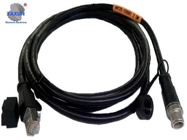
Plug and Play Signal Sensor Wiring Harness
A sensor communication wire harness, the wire material uses industrial drag chain grade CAT 5E network cable. One side of the port is a standard M12 circular connector with IP67 waterproof capability. The other side uses an RJ45 8P8C crystal head, and the wiring is the 568B line sequence in the EIA/TIA wiring standard.
A sensor communication wire harness, the wire material uses industrial drag chain grade CAT 5E network cable. One side of the port is a standard M12 circular connector with IP67 waterproof capability. The other side uses an RJ45 8P8C crystal head, and the wiring is the 568B line sequence in the EIA/TIA wiring standard.
Boiler high temperature signal transmission harness:
A boiler high-temperature image transmission harness and sensor. The transmission harness includes: at least one optical fiber harness. Thermal insulation layer; heat-resistant jacket. The optical fiber harnesses are closely arranged to form an integrated harness. The heat-insulating layer covers the outside of the optical fiber harness, and the heat-resistant sleeve covers the outer surface of the heat-insulating layer. The boiler high-temperature image transmission sensor includes: boiler high-temperature image transmission harness. Interface side. The transmission harness is connected to the interface end. The interface end includes a lens interface and a camera interface, which are respectively used to connect the lens and the camera. The camera collects the boiler image signal and transmits the image signal to the lens through the boiler high-temperature image transmission harness and interface end. The transmission harness and sensor can effectively reduce the impact of boiler temperature on the transmission signal through the heat insulation layer and high-temperature-resistant ceramics, and can transmit high-quality image signals through optical fibers.
Electronically controlled diesel engine integrated wiring harness design
The electronic control system is the “nerve center” of the electronically controlled engine, including sensors, controllers, actuators and control wiring harnesses. Control wire harness: The control wire harness is the hub that connects sensors, controllers and actuators as well as vehicle signals and power supply. The control wiring harness is divided into engine wiring harness part and vehicle wiring harness part. As environmental protection becomes more and more stringent, the emission requirements for diesel engines are getting higher and higher. The development of electronically controlled diesel engines is a good way to solve diesel engine emissions. In order to meet the needs of different users, various diesel engine manufacturers produce electronically controlled diesel engines of different models, different uses, and different electronic control systems. When performing performance debugging, the electronically controlled diesel engine needs to be debugged on the factory test bench. Different electronically controlled diesel engines require different test bench wiring harnesses due to different connector sizes and pin definitions. Too many test wire harnesses on the test bench will occupy the test bench space, affect the normal operation of the test, and are not conducive to the daily maintenance of the test wire harness. The design and production of integrated wiring harnesses for factory test benches of various electronically controlled diesel engines introduces the design and production of integrated wire harnesses for factory test benches that meet the needs of different electronically controlled diesel engines.
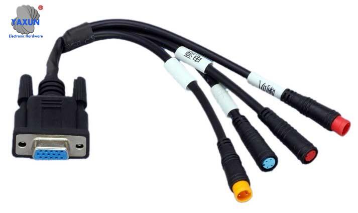
DB9 female to M8 signal sensor wiring harness
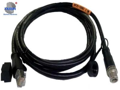
Signal Sensor Wiring Harness
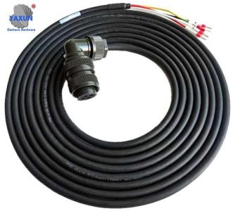
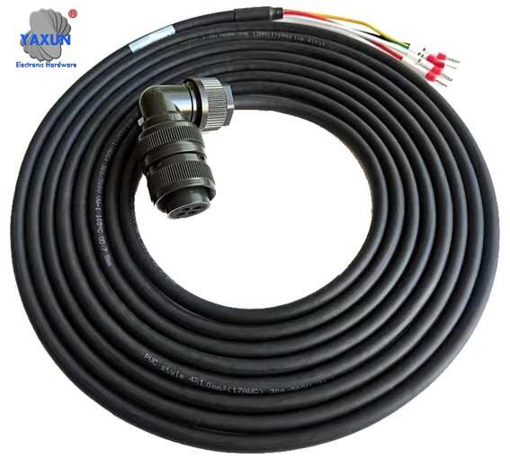
Motor encoder wiring harness
Multifunctional sensor transition harness:
The utility model discloses a multifunctional sensor transition wire harness. The multifunctional sensor transition harness includes: a wire; and a sensor female end connector, which is arranged at one end of the wire for connection with the sensor connector of the measured sensor. The sensor’s public connector is located at the other end of the wire. A single signal connector is located at the other end of the wire. and an oscilloscope connector, which is arranged at the other end of the wire for connection with the signal extension line of the oscilloscope. This multifunctional sensor transition harness adds a transition harness with multiple conversion connectors to enable signals to be output through multiple ports, avoiding various shortcomings of traditional wiring methods and improving the reliability of the signal line and the stability of the signal as much as possible.
Contact Us
Waiting for your email, we will reply you within 12 hours with valuable information you needed.
 English
 العربية
 Български
 中文(漢字)
 Čeština
 Dansk
Dansk Eesti keel
 Suomi
Suomi Français
 Deutsch
 Ελληνικά
 עברית
עברית Magyar
 Bahasa Indonesia
 Italiano
 日本語
日本語 한국어
한국어 Latīna
 Latviešu valoda
 Lëtzebuergesch
 Polski
 Português
 Română
 Русский
 Slovenščina
 Español
 Svenska
 ภาษาไทย
 Tiếng Việt
