As the basic network body of automobile circuits, the terminal connection harness still plays an irreplaceable role in the automobile electrical system.
Automotive Connecting cables are distributed in various corners of the car. According to the main structure, it can be divided into cab wiring harness, chassis wiring harness and engine wiring harness.
Among them, the door harness in the cab works under repeated expansion and contraction for a long time;
• Chassis wiring harness works in high and low temperature and mud-immersed environments for a long time;
• The engine wiring harness works in a high-temperature and high-oil environment most of the time, and must bear the impact of transient current at the moment the engine starts.
If the automobile wiring harness cannot adapt to work in these extreme environments, it will inevitably lead to fire, short circuit, corrosion and aging, 等, which will directly affect the driving safety of the car and lead to accidents. In order to ensure the safety of automobiles, the testing and verification of automobile wiring harnesses is particularly important. This article’s wiring harness engineer mainly introduces the research on the durability characteristics and contact voltage drop testing methods of wiring harnesses.
The main automotive wiring harness standards include QCn29005-1990 “Quality Classification of Automotive Low-Voltage Wire Harnesses”; QCn29009-1991 “Technical Conditions for Automotive Wire Connectors”; QC/T29106-2014 “Technical Conditions for Automotive Wire Harnesses”.
In terms of wire harness testing, China mainly follows the QC/T29106-2014 standard. しかし, this set of standards has many shortcomings in electrical performance testing:
For the contact voltage drop test in electrical performance testing, the method mentioned in the standard is not applicable in actual testing, because this method requires a lot of testing equipment and needs to be measured after thermal equilibrium. As for the durability characteristic test, there is no mention in the standard.
Aiming at the deficiencies in these two test items of the standard CLP performance test. Based on the QC/T 29106-2014 standard, this article proposes new durability characteristic testing and contact voltage drop testing methods, and conducts experimental verification on these two testing methods.
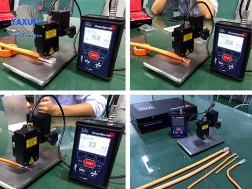
Wiring harness durability characteristics test chart
1 Durability test
The purpose of the durability characteristic test is mainly to ensure that the temperature of the wires cannot exceed the fault temperature after the load-type wire harness operates at full load for a period of time. And electrical equipment such as fuses, コネクタ, and relays in the circuit must not be burned out. There is no mention of durability characteristic testing in the QC/T29106-2014 standard.
By consulting relevant literature, the traditional durability characteristics testing methods are:
After inputting an overload current to the test circuit for a certain period of time, use a temperature sensor to measure the temperature of the wire. Judge whether the test is qualified by observing the temperature and appearance of the wire.
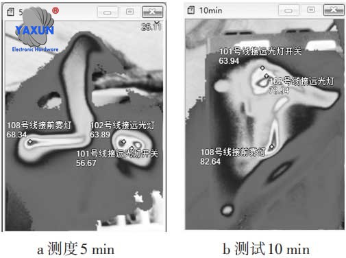
Thermal imaging diagram of durability characteristics test of automobile wiring harness
Temperature sensors are used in traditional durability characteristics testing to measure wire temperature. This method can only reflect the temperature of a certain measurement point of the conductor, but cannot reflect the temperature of the entire conductor. したがって, this article proposes a method of measuring wire temperature using an infrared thermal imager. This method can intuitively and quickly observe the temperature of the measured wire harness as a whole. Figure 1 is a schematic diagram of the improved wire harness durability characteristics test. The calculation formula for overload current is:
(1) In the formula: Io is the overload current; K is the overload current coefficient; IA is the rated current of the fuse. The overload current coefficient K is related to the type of fuse: K for Jcase and Mega fuses is 135%; for Midi and BF fuses, K is 145%.Figure 2 is a thermal imaging diagram of the durability characteristics test of the electrical box wiring harness of a certain vehicle model, and Figure 3 is a temperature trend diagram of the wiring harness. The wiring harness loop fuse is a 20 A Jcase fuse, and the overload current is:
Through testing, it was found that the maximum temperature of the wires in the electrical box wiring harness did not exceed 98°C after the overload current passed through for 30 minutes, which was less than the fault temperature of the wires of 105°C. The test results show that the electrical box wiring harness passed the durability characteristics test. This method can effectively test the durability characteristics of wire harnesses.
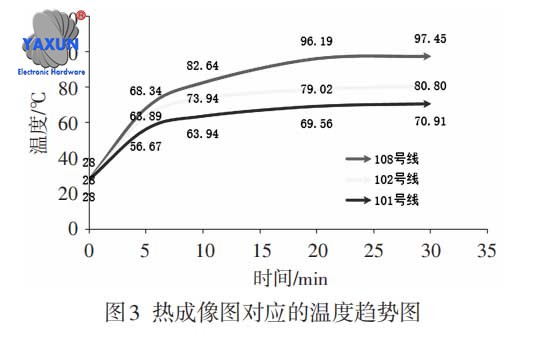
Temperature trend chart corresponding to the wire harness thermal image
The wire temperature T is related to the wire calorific value Q. The wire calorific value Q is calculated according to formula (2):
(2) In the formula: I is the calculated value of the wire current; R is the calculated value of the wire resistance; t is the energization time of the wire; ρ is the resistivity of copper; l is the length of the wire; s is the cross-sectional area of the wire.
The parameters of wires 101, 102, そして 108 in this test are shown in Table 1. Based on the data in Table 1, the I2R values of wires 101, 102, そして 108 are calculated to be 22.7, 293.6, そして 317.3 respectively, つまり, the heat generated by the wires is Q108>Q102>Q101. It can be concluded that the wire temperature T108>T102>T101 is consistent with the wire temperature trend measured by the thermal imager (Figure 3).
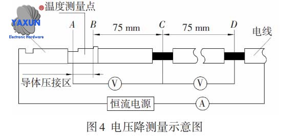
Schematic diagram of voltage drop measurement of wire harness
2 Contact voltage drop test of wiring harness terminals
1. Direct testing method
The QC/T29106-2014 standard stipulates the test method for the voltage drop of the wiring harness terminal contacts:
初め, connect the circuit according to the schematic diagram (Figure 4), look up Table 2 to determine the test current, and then pass a constant current through the circuit. When the difference in temperature readings of five consecutive temperature measurement points is less than ±2°C, the thermal equilibrium state is reached. At this time, measure the voltage between point A and point B, point A and point C, point C and point D respectively. The voltage drop in the conductor crimping area is calculated according to formula (3):
(3) In the formula: UAB is the voltage drop in the wire crimping area; UAC is the voltage drop between measurement point A and point C; UCD is the voltage drop between measurement point C and point D. According to the requirements of QC/T29106-2014, the calculated voltage drop UAB should not be greater than the voltage drop given in Table 2.
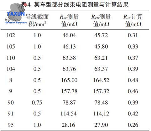
Wire harness resistance measurement and calculation results
Indirect testing method
The essence of the voltage drop at the wire harness terminal contact is the contact resistance generated when the terminal and the wire are crimped. Contact resistance includes three parts: shrinkage resistance, conductor resistance, and film layer resistance.
したがって, this article proposes a method to indirectly measure the voltage drop of the wiring harness terminal contact – resistance measurement method. This test method is simple to operate and can be completed with only a high-precision milliohmmeter. In this article, the wire harness resistance measurement uses the TH2516B low resistance tester with an accuracy of 1 μΩ.Figure 5 is a schematic diagram of the indirect measurement method. AB in the figure is the crimping area between the wire and the terminal. During the test, the contact resistance of the crimping area can be calculated by formula (4) by simply measuring the resistance between AC and CD.
(4) In the formula: RAB is the contact resistance of the wire crimping area; RAC is the resistance between measurement point A and point C; RCD is the resistance between measurement point C and point D.
Based on the voltage drops and test currents corresponding to wires with different cross-sectional areas given in QC/T29106-2014, which are the values in Table 2, the contact resistance of the corresponding crimp points of different wires can be calculated. as shown in Table 3. According to the requirement in the standard that the voltage drop UAB should not be greater than the voltage drop given in Table 2, the contact resistance of the crimping point measured and calculated in this indirect measurement method test should not be greater than the requirements in Table 3.
Table 4 shows the measurement results of some wires of a certain car model. It can be seen that the contact resistance RAB of all wire crimp points is less than the value in Table 3, つまり, the voltage drop between the wire and terminal contact meets the requirements of standard QC/T29106-2014. The test results show that the wire harness contact voltage drop meets the requirements, and this method can effectively conduct contact voltage drop testing.
3 結論
Taking QC/T29106-2014 as the test standard, a new test method is proposed to address the shortcomings of the standard electrical performance test method, and the following conclusions are drawn:
1) Traditional durability characteristic testing uses temperature sensors to record the wire harness temperature. This method can only measure the temperature at a certain point on the wire. The use of a thermal imager to measure wire temperature proposed in this article can dynamically and intuitively observe the temperature of the entire wire harness system including connectors, wires, and electrical equipment, and can quickly find the highest temperature point to analyze the durability characteristics of the wire harness;
2) The traditional contact voltage drop test uses a direct measurement method, which requires a lot of testing equipment and needs to be carried out after constant current is energized to reach thermal equilibrium. The method proposed in this article to indirectly measure contact voltage drop by measuring contact resistance only requires a milliohmmeter and does not require building a test circuit. More concise and efficient than traditional methods.
 English
 العربية
 Български
 中文(漢字)
 Čeština
 Dansk
Dansk Eesti keel
 Suomi
Suomi Français
 Deutsch
 Ελληνικά
 עברית
עברית Magyar
 Bahasa Indonesia
 Italiano
 日本語
日本語 한국어
한국어 Latīna
 Latviešu valoda
 Lëtzebuergesch
 Polski
 Português
 Română
 Русский
 Slovenščina
 Español
 Svenska
 ภาษาไทย
 Tiếng Việt
