Crimping is a very important process in automobile wiring harness production engineering. The crimping process is the core process of wire harness production, which can ensure the electrical connection between wires and terminals. This article mainly introduces the crimping process of automobile wiring harness terminals. The following is the main text.
The driving safety and reliability of automobile wiring harnesses should be fully considered during the structural design and production process. At the same time, the rationality of the vehicle assembly process and the possibility and rationality of the wiring harness production process must also be considered.
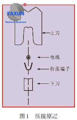
Crimping principle of terminal blocks
Crimping of current harness
There are two ways to connect wires and terminals: one is soldering connection and the other is crimping. Early production automobile wiring harnesses all used soldering connections. Especially when the production batch is small and the wiring harness is relatively simple, this connection process is often used. Nowadays, most wire harness manufacturers use the crimping process. Its advantages are: simple processing technology, suitable for mass production; reliable contact performance of the wire harness, long service life, purifying the working environment, and ensuring the physical and mental health of production workers.
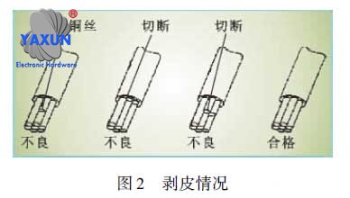
Stripping comparison of wire ends
1.1 Concept of crimping
Crimping is a very important process in automobile wiring harness production engineering. Crimping is an effective and reliable method of connecting electrical conductors. Crimping is an important process in producing wire harness components (circuits) from raw materials (terminals, wires and seals).
Crimping is an important process that determines the electrical and mechanical properties of terminals and wire connections.
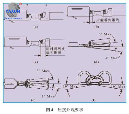
Crimp appearance of terminal blocks
1.2 Principle of crimping
Wire harness terminal crimping refers to the strong combination of wires and terminal contact surfaces through external force. The process is achieved by relying on the power of the crimping machine by crimping the upper and lower blades of the mold (as shown in Figure 1). It is actually the process of the terminal from free bending to corrected bending.2 Stripping and length determination of wire ends
2.1 Peeling requirements
As shown in Figure 2, the stripping of the end of the crimped wire must meet the following requirements:
(1) Moderate length
(2) Broken copper wires are absolutely not allowed
(3) It is not allowed to damage the original shape of the wire
Although wires of different specifications and different types of terminals require different stripping lengths, the stripping quality must meet the above requirements. Only in this way can the next process – crimping of wires and terminals be guaranteed.
2.2 Length determination
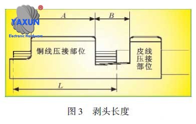
The determination of the stripping length at the end of the wire is shown in Figure 3, in mm. Stripping length L=(0.5-1.0)+A+B/2
Stripping requirements for wire ends
3 Crimp the wires and terminals
In automobile wiring harnesses, the crimping quality of wires and terminals is a very important process, which is directly related to the reliability of the wiring harness assembly and the driving of the car.
3.1 Factors that determine good or bad crimping quality
(1) Good electrical properties: low and stable electrical impedance; corrosion resistance.
(2) Good mechanical properties: high pulling force.
(3) Good physical properties: reasonable core deformation; moderate bell mouth; small burrs; suitable crimping aspect ratio.
3.2 Appearance requirements for crimping
(1) The part where the terminal is crimped to the wire core should have an upwardly curved arc angle near the end (أ) of the leather wire. This can ensure that the wire core is not damaged during the crimping process, and at the same time, the transition of the crimped wire core is good, and the B position is optional, as shown in Figure 4(a).
Crimping electrical and mechanical properties of terminal blocks
(2) The front end of the crimped wire core must meet two requirements:
① The crimping head is visible, which can more effectively ensure the pulling force of the terminal after crimping and meet its mechanical properties;
② The crimping tip cannot extend into the bonding area and self-locking area of the terminal, otherwise it will affect the assembly performance of the terminal and the sheath and prevent the terminal from being properly installed into the sheath. At the same time, it will also affect the ideal mating of male and female terminals, and sometimes lead to incomplete assembly and locking of the mating sheaths.
The crimping tip length value is determined by the characteristics of the terminal itself. Terminals of different specifications have different numerical requirements for protruding length, and terminals designed by different manufacturers also have different requirements for protruding length. The terminal specifications should be taken into consideration to determine the crimping length of the terminal. Small-sized terminals have shorter protruding lengths when crimping small-square wires. When crimping large-sized terminals to large-square wires, the crimping head length is relatively longer. The length of the protruding head is generally 0.5-1.0mm. But different manufacturers have different requirements. على سبيل المثال, DELPHI requires a protruding length of 0.5-1.0mm; YAZAKI requires a protruding length of 0.1-1.0mm; AMP requires a protruding length of 0.5-1.0mm; some of the more precise terminals are 0.13-0.51mm. MOLEX requires that the protruding length be visible to twice the outer diameter of the conductor core and cannot extend into the bonding area; KET requires that the protruding length is 0-2.0mm; JST requires that the protruding length must be visible. As shown in Figure 4(b).
The core and insulation of the wire should be visible at the same time between the rear end surface of the crimped wire core and the front section of the crimped insulation. عمومًا, it is best for the end face of the wire insulation to be in the middle of the opening, but it is absolutely not allowed that the wire core and insulation are not visible. As shown in Figure 4(c).
(4) The terminal after crimping may be extruded and deformed, causing the mating part to be deformed, but it must meet Figure 4(d) (upper and lower deformation), 4(e) (left and right deformation), and 4(f) (torsion deformation) requirements.
Cutting position for terminal wiring
3.3 Cross-section inspection after terminal crimping
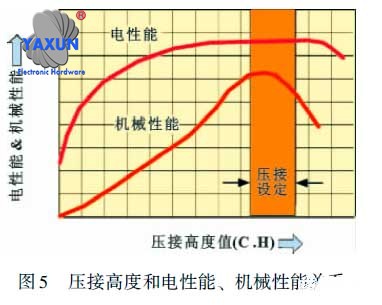
Research shows that when the blade is determined, the crimping height has a relationship with electrical and mechanical properties as shown in Figure 5. It can be seen that as the crimping height increases, the electrical and mechanical properties do not always increase. In a certain area, the electrical and mechanical properties reach their optimum and then gradually decrease.
After adjustment of the crimping mold for each wire and terminal in the wire harness, a cross-sectional inspection is required. The purpose of cross-section inspection is to find a reasonable crimping height to obtain optimal electrical and mechanical properties.
Specific methods: After the test piece passes the visual inspection, the test piece is cut, ground, pickled and other related operations in sequence on the special profile analysis equipment. أخيراً, observe the cross-section under a microscope with at least 20 times magnification and take photos.
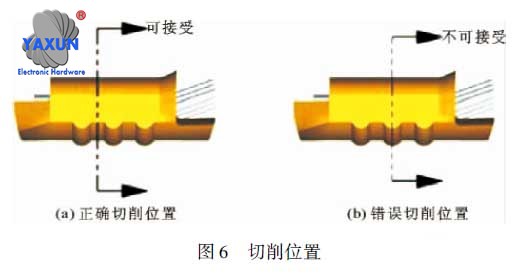
Note: The cutting part of the test piece should be selected close to the head of the terminal. If the terminal has reinforcing ribs, the cutting position must avoid the reinforcing ribs, as shown in Figure 6.
Crimp profile of terminal block
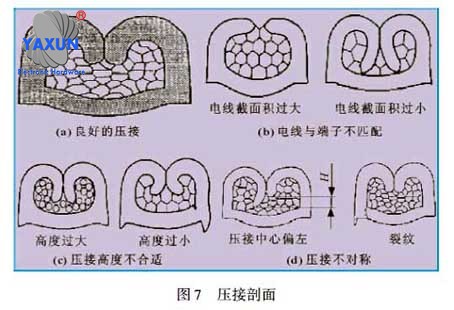
(1) Figure 7(a) is the ideal crimping section. Its characteristics are that the crimping wings are closed, the crimping wings are symmetrical, all core wires are deformed, the crimping wings do not hit the wall or bottom, the terminal material has no cracks, and the burrs are moderate. In this way, since there is no gap between the wire cores, air cannot easily enter, thus avoiding poor contact caused by oxidation of the surface of the wire core or contact with acidic substances in the air.
(2) Figure 7(b) shows that the cross-sectional area specification of the wire does not match the crimp terminal. When the cross-sectional area of the wire is large and the tail size of the terminal is small, the terminal cannot completely close the wire after crimping, and even individual wire cores are exposed outside the terminal, as shown on the left in Figure 7(b); when the cross-sectional area of the wire is small and the terminal When the size of the terminal tail is large, the terminal tail will curl excessively and contact the bottom or side wall after connection, as shown in the right picture of Figure 7(b).
(3) Figure 7(c) shows that the crimping failure is caused by improper adjustment of the crimping height. When the crimping height is adjusted too high, the wire core may be crimped incorrectly, resulting in poor contact between the wire and the terminal. As shown in the left picture in Figure 7(c). When the crimping height is adjusted too low, the crimping will be too hard, the bottom of the terminal will become thin, the sharp corners on both sides will be too large, and the strength of the terminal will be damaged.
(4) Figure 7(d) shows unqualified crimping caused by unqualified crimping mold or improper adjustment of the crimping mold. When the crimping mold is adjusted asymmetrically from left to right or the mold is made asymmetrically, it will cause the top of one side of the terminal to be rolled into the wire core too much, as shown in the left picture in Figure 7(d). When the crimping die is improperly adjusted, it will also cause the lower corners of the terminals to be cracked and the bottoms on both sides to be asymmetrical.
3.4 Tension test of crimping quality of wires and terminals
The most common and intuitive quality inspection method for wire harness terminal crimping is tension inspection. The tensile strength inspection standards after crimping different wire cross-sectional areas and different specifications of terminals are shown in Table 1.
Sealing ring wiring crimping
3.5 Crimping of wire insulation and terminal blocks
The crimping technology of wires and terminals also includes the crimping of the insulation part of the wires and the terminals. In addition to the crimping of a single wire, there is also the crimping of two or more wires. Specific inspection methods also adopt cutting sections for inspection. The standard for common leather wire crimping is shown in Figure 8.
The left column in the picture shows the cross-sections with good crimping. The requirements are that the crimping is symmetrical, the plastic skin is not damaged, and the crimping wings surround the plastic wire to provide sufficient strength support.
(2) The crimped sections in the two columns on the right side of the picture are unqualified. It can be roughly divided into the following situations:
① During the crimping process of terminals and wires, if the crimping mold is adjusted too low, the insulation will be pressed through the top of the terminal, as shown in Figure 8(a). This can easily damage the core of the wire. لذلك, the quality of this crimp is a substandard crimp.
② During the crimping process of terminals and wires, if the crimping mold is adjusted too high, the insulation of the wires will not be crimped tightly, as shown in Figure 8(b). During the use of this kind of crimping, the root of the crimping between the wire core and the terminal is easy to break. لذلك, this kind of crimping is also an unqualified crimping.
It is not difficult to see from the above analysis that the crimping connections in Figure 8(c), (d), (e), (f), (g), and (h) are all unqualified crimping connections.
It should be noted that in the U-shaped and laminated crimping of double wires, if the cross-sectional areas of the two wires are different. During the crimping process, the smaller cross-sectional area should be at the bottom and the larger cross-sectional area should be at the top.
In addition to the common ones mentioned above, there are some other crimping methods for the insulation part, as shown in Figure 9, and the judgment criteria are the same as above.
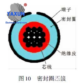
The crimping of insulation also includes the crimping of insulation, sealing rings and terminals. The specific requirements are: provide firm support for the sealing ring; there are no scratches or cuts on the neck and ribs of the sealing ring; the plastic wire crimping wings are not allowed to penetrate the neck of the sealing ring. As shown in Figure 10.
 English
 العربية
 Български
 中文(漢字)
 Čeština
 Dansk
Dansk Eesti keel
 Suomi
Suomi Français
 Deutsch
 Ελληνικά
 עברית
עברית Magyar
 Bahasa Indonesia
 Italiano
 日本語
日本語 한국어
한국어 Latīna
 Latviešu valoda
 Lëtzebuergesch
 Polski
 Português
 Română
 Русский
 Slovenščina
 Español
 Svenska
 ภาษาไทย
 Tiếng Việt
